Leadtek
TV2000XP Expert modification by smdg.
DISCLAIMER: THIS INFORMATION IS PROVIDED ON THE STRICT AS-IS BASIS. THE
AUTHOR OF THIS PAGE AND PHOTOGRAPHS DECLINES ANY RESPONSIBILITY AND
ANY DAMAGE THAT MAY RESULT OUT OF READING AND/OR USING THE
INFORMATION CONTAINED THEREIN.
DO NOT ATTEMPT THIS IF YOU HAVE NO EXPERIENCE WITH SURFACE-MOUNT
COMPONENTS.
This modification was done on a Assy rev A, PCB Rev D card.
From the electrical standpoint, the modification consists of adding a
voltage regulator to supply local, regulated +5V power to the TV tuner.
The regulator is powered from the PCI slot's +12V power rail.
The pictures
(Click on the thumbnail pictures to enlarge.)
General view
Top side of the card: 
Bottom side of the card: 
Close view on the regulator
The regulator is soldered to the ground copper layer on the bottom side
of the card, there was no suitable place on the top side of the card: 
The connection to the +12V power rail at the PCI slot
 ,
implemented with a copper wire.
,
implemented with a copper wire.
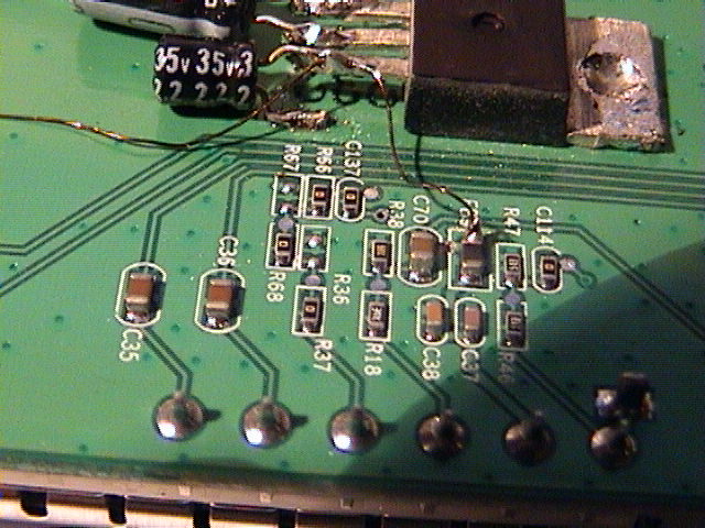
The connection to the tuner
The regulated +5V is fed to the tuner through the original power
decoupling LC networks implemented on the board. These LC networks were
powered from the general board's +5V power rail; the vias
connecting to the board's +5V layer have been destroyed.
The connection is done with a copper wire.
The first:  , view at
180°:
, view at
180°: 
The second:  , view at
180°:
, view at
180°: 
Notes
- Was used a regulator equivalent to the LM7805, in a TO220
package. Soldering it to the copper layer provides a good heat
dissipation path.
- The filtering capacitors at the input and the output should be
selected according to the regulator's datasheet. I have used some
compatible parts that I had at hand: 10uF at the input and 2.2uF at the
output.
- The connection was done with a 0.18mm isolated copper wire.
- Different irons are expected to be used to solder the regulator /
the capacitors, and the wire to the board.


 ,
implemented with a copper wire.
,
implemented with a copper wire. , view at
180°:
, view at
180°: 
 , view at
180°:
, view at
180°: